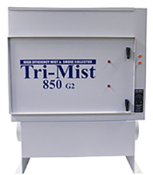
TRI – MIST 850 Manual
Read this manual carefully before attempting to install or operate the Tri-Mist mist collector series. Retain these instructions for future use. Instruction Manual Subject to Revision. Please contact us for the latest edition
SAFETY RULES
Follow all electrical and safety codes as well as the National Electric Code (NEC), and the Occupational Safety and Health Act (OSHA). All electrical connections and wiring should be performed by qualified personnel only.
Make sure to consult with the machine tool manufacturer to confirm that the Tri-Mist is compatible with the machine tool and fire suppression equipment before installing the Tri-Mist.
The electrical power to the Tri-Mist must be wired into the
emergency stop on the machine tool.
Safety:
Any individual operating the Tri-Mist 850 is strongly recommended to read and understand the information supplied in the installation manual prior to using the mist collection system to avoid incorrect operation of the equipment or personal injury.
While Tri-Dim Filter Inc. has made every effort to provide information regarding the safety for any and all individuals, this manual may not cover all possible contingencies regarding installation, operation and maintenance.
Warning Classifications:
Danger- Indicates an imminently hazardous situation which, if not avoided, will result in death or serious injury.
Warning- Indicates a potentially hazardous situation which, if not avoided, could result in death or serious injury. Examples of warning notices include hazardous voltage, electrical current, temperature or other conditions that are associated with the equipment or operation of the equipment.
Caution- Indicates a potentially hazardous situation which, if not avoided, may result in minor or moderate injury.
Safety Precautions:
Warning– Cutting oil in the machining process should not be used unless a fire suppression system has been installed on the machine tool by a certified fire prevention company.
Warning– This Mist Collector is not explosion proof, do not use in explosive atmospheres.
Warning– The following is a list of suggested safety precautions:
- Read and follow all instructions and safety warnings in this Tri-Mist manual prior to using this systems
- Read and follow all instructions and safety warning provided by the machine tool manufacturer for the safe operation of the machine tool
- Make sure to consult with the machine tool manufacturer to confirm that the Tri-Mist is compatible with the machine tool fire suppression equipment before installing the Tri-Mist system.
- The Tri-Mist System must be wired in the emergency stop switch on the machine tool.
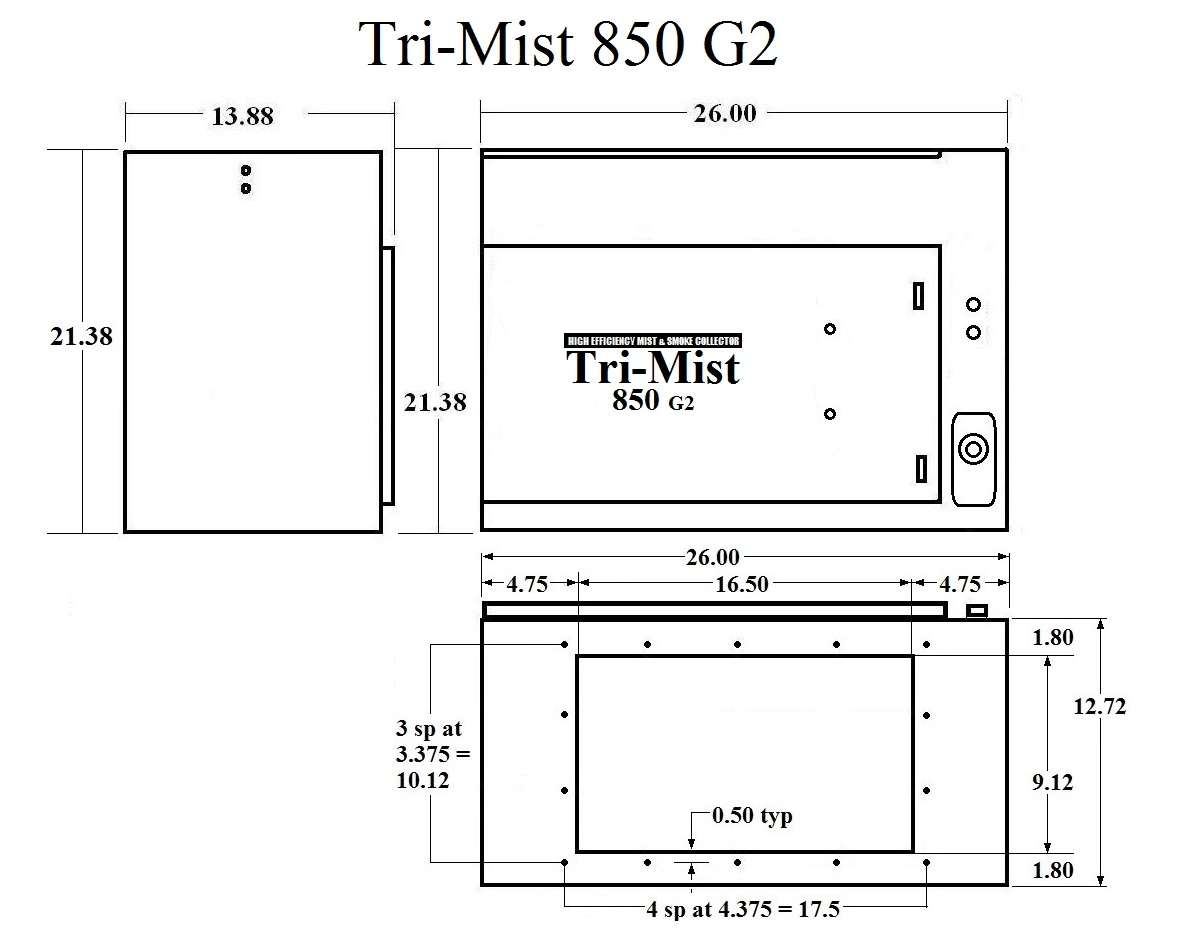
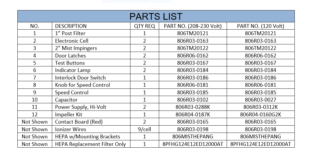
SPECIFICATIONS
DIMENSIONS: Cabinet – 26”L x 13.75”W x 21.38 H
INLET OPENING: 16.70” X 9.10”
WEIGHT: 95 lbs Installed
125 lbs Shipping, Class 85
EFFICIENCY: Up to 99% per ASHRAE 52.1
AIRFLOW: 50 – 850 CFM
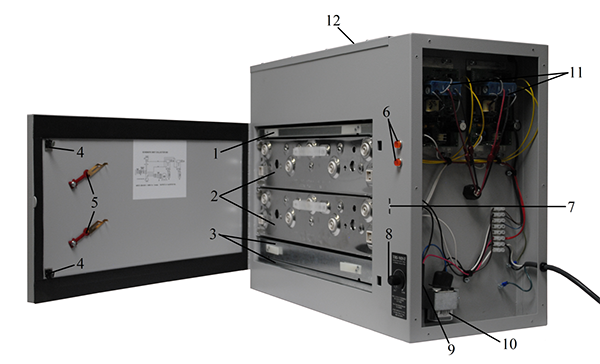
FILTRATION: 1st Stage – 4” impinger
2nd Stage – ESP
3rd Stage – ESP
4th Stage – 1” thick post filter
5th Stage – Optional HEPA filter – 99.97%
efficient.
POWER SUPPLY: High Voltage power supply is Solid-state and self-
regulating.
IMPELLER : Backward Curved, vibration-free, direct drive
rated at 1050 cfm.
POWER: 208 -230 Vac, 50 HZ/60 HZ, 2 Amps, single phase
or
120 Vac, 60 HZ, 4 Amps, Single phase
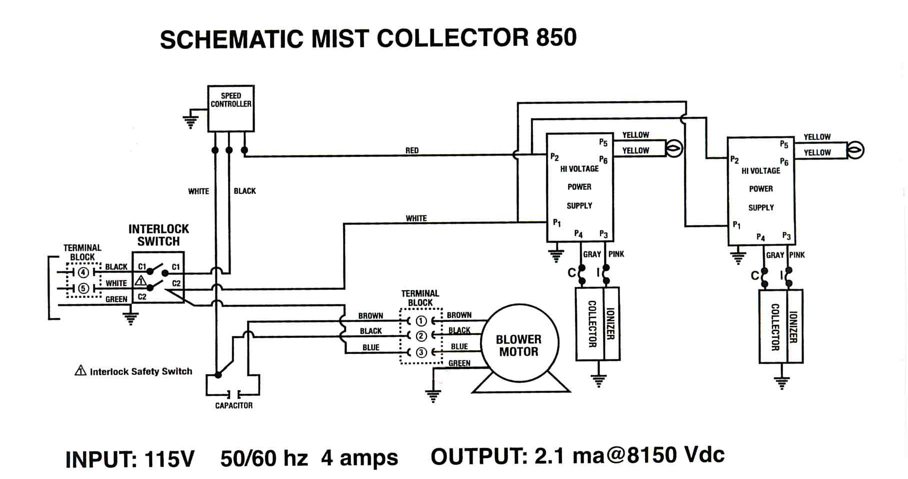
NOTE: Tri-Mist units are not dual voltage, See schematic on the inside of the cell access door to determine the voltage of your Tri-Mist 850.
INSPECTION
Inspect the Tri-Mist 850 for any shipping damage that may have occurred. Any damage should be noted and the carrier notified immediately.
TOOLS AND EQUIPMENT REQUIRED
The following list of tools that would be needed for a typical installation:
- Drill
- Reciprocating Saw
- Hand tools
PLANNING THE INSTALLATION
WARNING- This Mist Collector is not explosion proof, do not use in explosive atmospheres.
- The Tri-Mist 850 should be located with consideration for access to the hinged door and the electrical compartment cover. The filter access door requires a minimum of 20” clear in front of the door.
- The side access cover on the right hand side should be accessible, if possible.
- Mount the Tri-Mist 850 as far from the chip conveyor opening as possible.
- The Tri-Mist 850 is equipped with a 10ft power cord. Make sure the power source is within 10 ft of the Tri-Mist unit and that the power source voltage is compatible with the Tri-Mist 850 that was ordered. The Tri-Mist 850 is not dual voltage; check the schematic label on the inside of the filter access door.
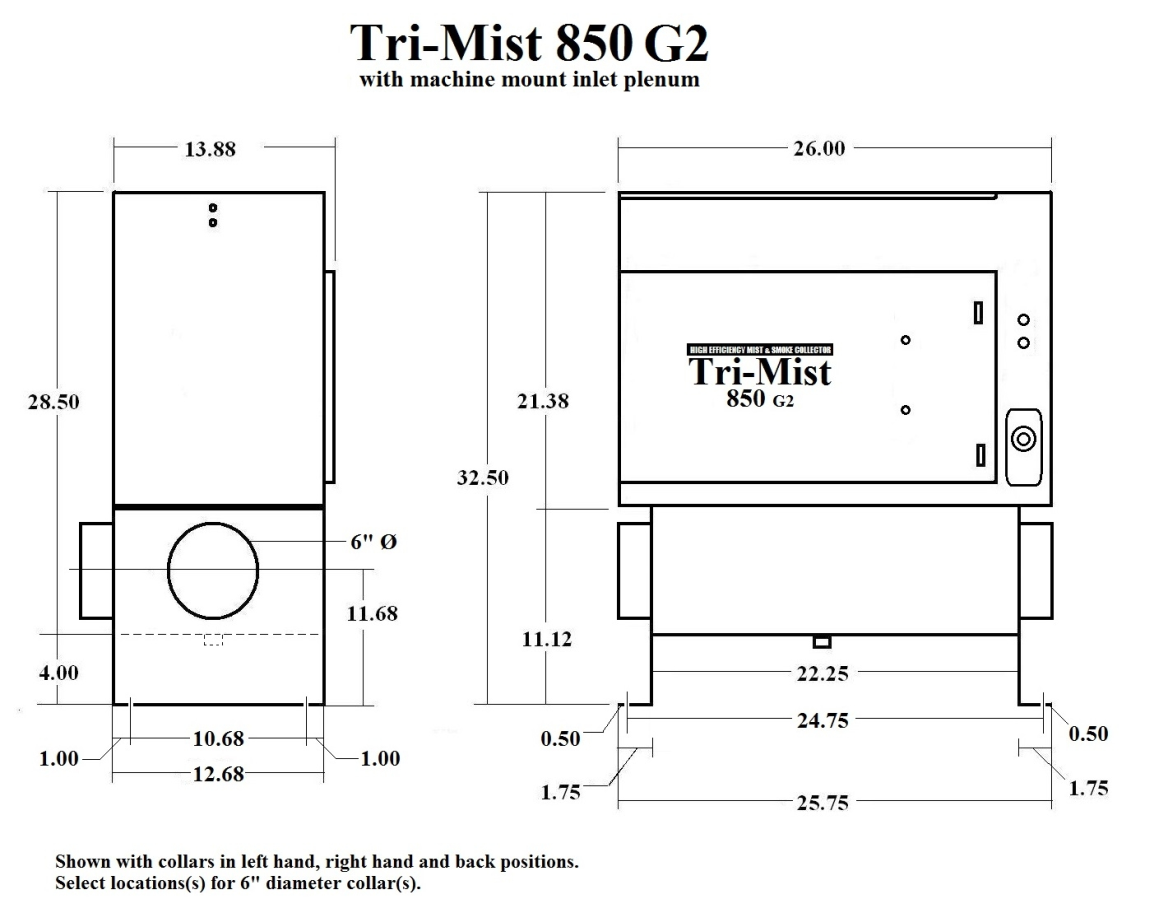
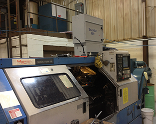
DIRECT MOUNT TO MACHINE ENCLOSURE
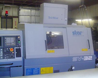
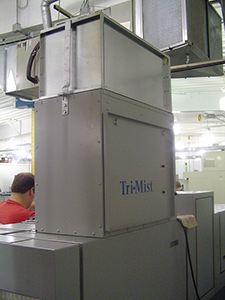
Direct Mount on Swiss lathe
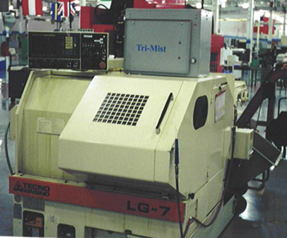
Tri-Mist 850 shown on a high-speed grinder.
DIRECT MOUNT INSTRUCTIONS
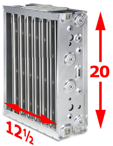
Carefully remove all filters and ESP cells from the Tri-Mist 850. Position the Tri-Mist 850 on the machine tool in the desired position.
1. Use the inlet opening and the mounting hole pattern on the bottom of the TRI-Mist 850 as a template to mark the inlet and mounting holes to be cut into the enclosure. NOTE: The inlet opening in the machine tool does not need to be as large as the inlet of the Tri-Mist 850. It is recommended that the inlet opening be a minimum of 32 square inches.
2. Use a .281 Dia drill bit to drill the mounting holes for the ¼-20 bolts used to secure the Tri-Mist 850 to the machine tool. There are 14 holes in the inlet flange of the Tri-Mist 850. It is recommended that a minimum of four be used to secure the Tri-Mist 850.
3. Apply the silicone sealant provided between the enclosure and the Tri-Mist 850. Bolt the Tri-Mist 850 to the enclosure.
4. Plug the Tri-Mist 850 into the correct power source. Note that the Tri-Mist 850 is not dual voltage. The schematic on the inside of the filter access door has the correct voltage for the Tri-Mist 850.
5. Replace the filters and ESP cells. Make sure that the airflow arrows point up.
DUCTED INSTALLATION
When direct mounting the Tri-Mist 850 is not possible or desired, the Tri-Mist 850 can be installed with a plenum option bolted to the Tri-Mist 850 inlet.
Tri-Mist 850 shown with optional Plenum and Machine Mount Stand
This plenum has a drain and collars to connect to flex ducting.
We recommend direct mounting when possible and limiting duct length when ducting is necessary.
INSTALLING THE PLENUM / STAND
Typically the plenum stand is installed at the factory. If it is to be installed in the field, attach the plenum to the inlet opening using the supplied gasket and ¼ -20 hardware.
Tri-Mist 850 shown with optional plenum / machine mount stand.
Note the drain on the bottom of the plenum.
CEILING MOUNT
WARNING For ceiling mounting, you must consider the weight of the Cool Blaster Mist Control system, the ductwork and oil being collected. All ceiling support members must be sized to properly support the unit, ductwork and drain hardware.
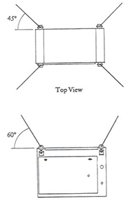
The ceiling hanging kit option provides 4 brackets and eyebolts. This allows the Tri-Mist 850 to hang from the ceiling structure.
We recommend direct mounting when possible and limiting duct length when ducting is necessary.
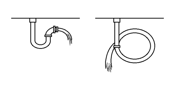
DRAIN INSTALLATION
The Tri-Mist 850 plenum has a ½ inch pipe thread (female) fitting for a drain. A P-trap is required for the metal working fluids to drain properly.
Prime the P-trap with the metal working fluid to avoid air being drawn through the plenum. The P-Trap can consist of a loop in a PVC hose or a hard pipe.
INSTALLING THE MACHINE MOUNT STAND
Carefully drill the required four holes in the machine tool to attach the plenum/stand to the machine tool. Carefully lift the Tri-Mist 850 onto the machine tool. Bolt the Tri-Mist 850 to the machine tool using 3/8” nuts, bolts and lock washers.
ELECTRICAL INSTALLATION
DANGER ELECTRICAL SHOCK HAZARD
Tri-Mist 850 system should only be installed by a qualified technician in accordance with the National Electrical Code (NEC), and the Occupational Safety and Health Act (OSHA). Improper electrical installation may damage equipment and can create a hazard causing possible injury or death.
The Tri-Mist 850 System must be wired into the emergency stop switch on the machine tool.
Cord Connected
The Tri-Mist 850 is equipped with a 10-foot power cord. The 115 / 120 volt model includes a standard 15 amp rated plug. The 208-230 volt model is shipped with a 10 foot power cord without a plug. A field supplied plug will need to be provided to match the 208-230 volt power outlet. Please note that the Tri-Mist 850 is not dual voltage.

INSTALL HEPA FILTER OPTION
1. Install the two anchor brackets to the center of both sides of the unit. The ¼ – 20 bolts must be removed from the side panel and reused to install the brackets.
2. Center the HEPA filter on top of exhaust grille with gasket side down.
3. Install the HEPA retainer brackets by hooking one end to the filter frame and bolting the other end to the anchor brackets.
START UP
1. The Tri-Mist 850 is equipped with a variable speed controller. Run the Tri-Mist 850 on the lowest speed that will provide negative pressure in the machine tool enclosure.
2. The indicator light should be on when the blower is running.
3. The Tri-Mist 850 is equipped with two test buttons to verify that the electronic filtration system is energized. Push each test button and listen for an arching sound. This indicates that the filtration system is energized.
Maintenance Procedures for Tri-Mist
Warning- Excessive accumulation on the filters (impingers and ESP cells) could result in fire damage
Caution- Be careful when handling the electronic cell, the metal edges may be sharp. Wear protective gloves when handling. Be careful not to damage the electronic cell, grip the cell on the frame so thin collector plates are not damaged.
Caution- Tri-Mist 850 has an interlock safety switch that disconnects electrical power to the filters when the filter access door is opened. To reduce the risk of electrical shock, do not perform any service other then filter cleaning unless power to the Tri-Mist 850 and the machine tool has been safely disconnected and you are qualified to do so.
During the first month of operation, inspect the mist impingers and the electronic cells to help determine proper maintenance interval. When there is a buildup of coolant, it is time to clean the filters. In general, to maintain peak performance, the Tri-Mist 850 filters (impingers and ESP cells) should be cleaned a minimum of four times per year. This will insure maximum mist collection efficiency. In some High Pressure Coolant applications the cells may need to be cleaned more frequently.
Parts Washer Method
The mist impingers and electronic cells can be cleaned with a parts washer. Make sure that the cleaning fluid used is aluminum safe and the maximum pressure does not exceed 65 psi. I would recommend an aqueous parts washer rather than a solvent based washer.
It is very important that the cell be rinsed very well to insure that all detergent is rinsed off. Check that the Ionizer wires are clean and smooth.
Manually Cleaning the Electronic Cells with a Spray Bottle
Important: make sure that the detergent used is safe for aluminum and that all of the detergent is rinsed off with hot water.
1. Spray detergent on the electronic cell until all surfaces on the cell are covered with detergent; allow the detergent to work on the cell for 7-10 minutes before rinsing.
2. Rinse cell with hot water making sure that no detergent residue remains.
3. Using a cloth, wipe each ionizer wire to remove any residual oil or water.
4. On very dirty cells it may be necessary to repeat steps 1 through 3.
5. Replace cell back into Tri-Mist unit after allowing cell to drip dry for 20 minutes.
Note: If water-soluble machining fluids are used, it would be best to spray a light coat of oil on to the electronic filter after washing. LPS or WD40 in a spray bottle are very effective. This light coating of oil makes the aluminum cell easier to clean for the next cleaning.

Electronic Cell Inspection
1) Check that all 9 ionizer wires are in place and that there is no buildup of dirt on the wires. The ionizer wires should feel smooth. If they feel rough then there is a coating on dirt on the wires that needs to be removed either rewash the cells and wipe the wires with a cloth our use 600 grit emery paper and carefully go over the wires. If there are missing wires they should be replaced, see ionizer wire replacement on the following page.
2) Check that the collector plates are secured to the support tubes. Loose collector plates cause arcing and can only be repaired at the factory.
3) Check that there are no foreign objects wedged between the collector plates.
4) If the cell appears to be clean and in good shape, then simply blow compressed air through the cells. Many times a foreign object is hard to see and the compressed air can dislodge it.
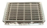
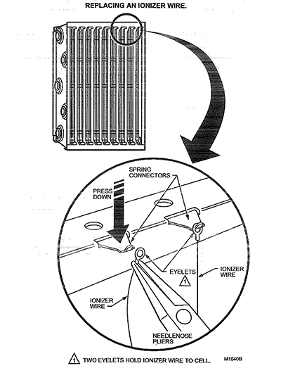
Replacing ionizer wires
Broken or bent ionizer wires can cause an electrical short to ground, often resulting in visible arcing. Do not use cells until broken wires are removed. Cells can be used with one missing wire, but replace the wire as soon as possible.
Replacement wires are supplies, cut to length with eyelets on both ends for easy installation.
1. Hook the eyelet on one end of the wire over the spring connector on one end of the cell. See figure.
2. Hold the opposite eyelet with needle nose pliers and stretch the wire the length of the cell. Depress the opposite spring connector and hook the eyelet over it.
Manually Cleaning the Mist Impingers
Wash with a degreaser and rinse with hot water. Allow to dry or use compressed air to blow excess water off. The Mist impingers can be cleaned the same way you clean the electronic cells.
Cabinet
Using the same detergent, clean the inside and outside surfaces of the Tri-Mist once per year.
TRI-MIST 850 G2 (Generation 2)
CERTIFICATE OF WARRANTY
Tri-Dim Filter Corporation warrants the Tri-Mist 850 air cleaner to be free of defects for a period of four years from the date of purchase by the customer, when used under normal conditions. This warranty is valid under the following conditions:
1. Purchaser will contact Tri-Dim Filter Corp for authorization and a return goods number and shipping address.
2. Proper Delivery: All transportation charges submitted under this warranty shall be borne by the purchaser. Returned products shall be shipped in either its original packaging or in packaging that assures protection of the product. The return number must be clearly visible on the outside of the carton.
3. Serial Number Intact: A showing by the purchaser that the serial number has not been altered or removed.
4. Misuse: A showing by the purchaser that the product has not been involved in an accident, freight damage, misused or operated contrary to the instructions in the owner’s manual.